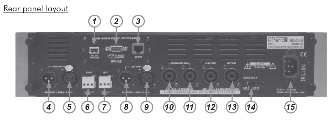
1) External volume control on 2 pole euroblock : here you can connect a standard 10 kÙ linear
potentiometer, wired as an adjustable resistor, using a shielded cable. Connect the shield to
the – connector. When enabled in the settings menu, this external potentiometer allows you to
increase or decrease the master volume in 2 dB steps. Enabling the external volume control
automatically disables the front panel master volume control. Serial port volume control will
also be disabled. When no external potentiometer is connected while the external volume
control feature is enabled, or the connecting cable is faulty, or the value of the potentiometer is
out of range, the 3 SGL/ERROR LED’s on the front panel will light up red and blink. The display
will show “INVALID EXT. VOL” and the audio signal will remain muted until the connection has
been repaired or the external volume control has been disabled in the settings menu.
2) RS232 port on DB9 connector. Standard serial port connector for programming, external
control and firmware updates using our firmware update program available online. Port settings
are fixed at 19200 baudrate, 8 databits, no parity, no handshake. LF (line feed), BS (backspace)
and ECHO are not enabled but can be enabled using an RS232 command string. More
information in the RS232 commands chapter.
When the text returned via RS232 is garbled or no communication is possible, adjust your
communication parameters to match those of the unit. If you are not familiar with RS232
communication, serial cables and communication parameters, ask for assistance from a
qualified engineer!
!!!WARNING!!!
Connecting a computer or any other similar control device via RS232, may cause a severe ground
loop! Ground loops may cause erratic behavior and eventually damage your system components.
3) APNET connector. For future use. DO NOT connect any kind of computer network cable here.
It will result in malfunction or damage to your network!
4) Right channel XLR male input connector.
5) Right channel XLR female input signal connector.
6) Right channel balanced input on euroblock. Items 4, 5 and 6 are hardwired internally and can
be used to create a daisy chain for connecting even more amplifiers.
7) Left channel balanced input on euroblock. Items 7, 8 and 9 are hardwired internally and can
be used to create a daisy chain for connecting even more amplifiers.
8) Left channel XLR male input signal connector.
9) Left channel XLR female input connector.
10) Subwoofer output on 4 pole Speakon® connector. Pins 1+ and 2+, as well as 1- and
2- are connected in parallel. Minimum load impedance is 4 ohms on each Speakon®
connector.
11) Subwoofer output on 4 pole Speakon® connector. 1+ and 2+, as well as 1- and 2- are
connected in parallel. This connector carries exactly the same signal as 10 and is hardwired
internally. Minimum load impedance is 4 ohms on each connector. In case you want to use
2 pieces 4 ohm subwoofers, then wire them independently. One sub connected to 10, the
second to 11. Always make use of the 4 connection pins (1+ and 2+, 1- and 2-) to avoid
contact burn-in caused by the extreme currents flowing through these connectors!
12) Right speaker output on 4 pole Speakon® connector. 1+ and 2+, as well as 1- and 2- are
connected in parallel. Always make use of the 4 connection pins (1+ and 2+, 1- and 2-) to
avoid contact burn-in caused by the extreme currents flowing through these connectors!
13) Left speaker output 4 pole Speakon® connector. 1+ and 2+, as well as 1- and 2- are
connected in parallel. Always make use of the 4 connection pins (1+ and 2+, 1- and 2-) to
avoid contact burn-in caused by the extreme currents flowing through these connectors!
14) Ground lift switch: this switch normally stays in the “EARTH” position. In case you have
created a ground loop, you can switch it to the “LIFT” position, to help you find the source of
the ground loop. However, when the ground loop is severe, activating the switch will not help
much, and eventually one or more system components may fail. When excessive noise, hum
or system instability occurs, power off all devices, and start connecting all units individually.
Tuners connected to an outdoor antenna or a cable signal distribution system, computers,
serial control devices and laptops are the usual suspects.
15) Mains inlet connector: plug in the supplied mains cable here. The mains fuse is located
inside the unit and can be accessed by removing the top cover of the unit. For authorized
personnel only! When the fuse blows regularly, check your system first, remove any ground
loops caused by faulty installation. Always check for short circuits on your speaker lines,
audio signal lines and other connections.
|